Vehicle Indicator circuit
The
project illustrated below helps to find out nearby person or vehicle
and make them visible to one another. It can be used in various
applications for pedestrians, runners, bicyclists, motorcyclists,
vehicles etc.
Most
of the time during the night when the roads are badly lit the risk of
accidents increases. Sometimes it happens that our vehicle breaks down
and we need help. In such conditions this reflector can be used which
automatically gets turned ON when it receives light from another vehicle
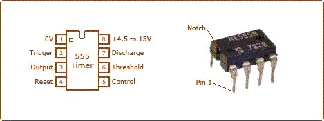
passing nearby. The circuit is based on 555 timer IC and uses a NE555 version of it. The pin diagram of the IC is shown in the image
When
ambient light is dim a potential drop occurs across the light dependent
resistor (LDR) below the level set by VR1. Due to this the reset
terminal (PIN4) of NE555 goes high to enable the oscillator.
In
other words we can say that in the presence of light, the resistance at
PIN4 of IC1 is very low. Hence no signal is passed to PIN4 of IC1 so
the voltage at pin 4 becomes equal to zero. As a result of this low
voltage the circuit remains OFF and in the darkness vice versa occurs so
PIN4 of IC1 becomes high and we get the output. this circuit can also be used as emergency night light, which puts on automatically.


No comments :
Post a Comment