Breaking News

Receive all updates via Facebook. Just Click the Like Button Below...

Showing posts with label IC. Show all posts

September 16, 2014

Vehicle Indicator circuit

Vehicle Indicator circuit


The project illustrated below helps to find out nearby person or vehicle and make them visible to one another. It can be used in various applications for pedestrians, runners, bicyclists, motorcyclists, vehicles etc.
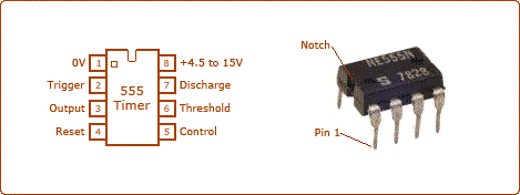
Most of the time during the night when the roads are badly lit the risk of accidents increases. Sometimes it happens that our vehicle breaks down and we need help. In such conditions this reflector can be used which automatically gets turned ON when it receives light from another vehicle passing nearby.  The circuit is based on 555 timer IC and uses a NE555 version of it. The pin diagram of the IC is shown in the image


 The reflector circuit consists of Light dependent resistor (LDR), timer IC (NE555), some bright LED’s and Transistor (BC549) which is used as buffer. In this project 555 timer is configured in oscillatory mode.
When ambient light is dim a potential drop occurs across the light dependent resistor (LDR) below the level set by VR1. Due to this the reset terminal (PIN4) of NE555 goes high to enable the oscillator.
In other words we can say that in the presence of light, the resistance at PIN4 of IC1 is very low. Hence no signal is passed to PIN4 of IC1 so the voltage at pin 4 becomes equal to zero. As a result of this low voltage the circuit remains OFF and in the darkness vice versa occurs so PIN4 of IC1 becomes high and we get the output. 


this circuit can also be used as emergency night light, which puts on automatically.
Read more ...

June 17, 2014

Cell Phone Controlled Home appliances

Cell Phone Controlled Home appliances

Many of us face problem when we out of our home like if we want to on the motor, so that when we reach home water will be filled in over head tank or we want to on other appliances like light fan etc.
Hence to solve this problem we have describe a simple circuit which will on your device or appliances remotely and it will become off automatically after preset time interval.
Many circuits have been developed so far to solve this problem but main advantage of this circuit is uses readily available components and this circuit is not expensive as well because this circuit is made using without microcontroller.

This circuit is based on two IC's namely MT8870 which is DTMF decoder IC and another is NE555 timer which is wired as monostable multivibrator with few more components like crystal, relay, resistors and capacitors.

How to operate a device remotely
In this circuit for operating a device we will require two cell phone, one will be with us from which we will call on the other cell phone which is connected to device. And other cell phone will be connected to the device in auto answer mode. For operating the device call on the cell phone which is connected to the device as this cell phone is in auto answer mode it will pick up the call automatically . When ring stop dial number 7 from the keypad of the mobile from which you are calling. Now the device connected to it with the relay start operating and will become off automatically after certain time period.

Working of circuit

Connect the cell phone  with the head phone or ear phone properly at mobile phone audio jack.  Now when you call on the mobile connected with device at the receiving end DTMF decoder IC will provide a high pulse at pin 15 after detecting the valid tone pair. This will trigger the pin 2 of IC2 and its output will go from high to low. This in turn make the output pin 3 of IC2 high and the transistor T2 connected to it start conducting because of this relay energise and device become on. The time period for which device remain on can be adjusted with the help of variable resistor VR1 and capacitor C4. By increasing or decreasing the value of variable resistor and capacitor  time period can be increased or decreased. This can be calculated by the below formula-
Time period = 1.1*VR1*C4 in seconds
In this circuit transistor T1 will only conduct when all the outputs pin 11, pin12, pin13 and pin15 will become high simultaneously with the help of diode D1 to D5. This can only be done by pressing the number 7 through DTMF decoder. The DTMF signal send from the dialler mobile end is decoded by the DTMF decoder and its respective BCD value appear at the output on pin 11, pin12, pin13. That's  why to on the device we are using number 7.


Read more ...

May 25, 2014

SOME USEFUL TIPS TO GOOD SOLDERING

SOME USEFUL TIPS TO GOOD SOLDERING


SOME USEFUL TIPS TO GOOD SOLDERING

1.       The two surfaces to be soldered should be thoroughly cleaned and made free from any dust, grease or oil. Infact, thorough cleaning of the PCB before beginning the soldering operation and proper tinning of the component leads at the time of soldering that Component achieves good results.

2.       A small quantity of flux may be applied on the surfaces to be soldered. It is the function of the soldering flux to keep away any oxide film during soldering operation and allow the two surfaces to make a metallic contact and alloy with each other. The flux residue should be removed after the soldering is done.

3.       One of the most common problems in soldering is the application of insufficient heat. The alloying action in soldering cannot be achieved without a uniform distribution of heat between the solder and the metal being soldered. If hot solder is applied to a cold metal or a cold solder is applied to a hot metal, there can never be a proper soldering action. Soldering will be proper only when the solder alloy is hot enough to remain in a liquid state as soldering is being done. To achieve a proper wetted soldered joint, heat up the component terminal end slightly (Remember not to exceed the component lead temperature beyond the safe recommended temperature. Excessive temperature can often damage sensitive semiconductor devices) and apply solder alloy right onto the component lead end instead of applying it on the soldering iron tip. Now with the soldering iron tip, melt the solder so that it flows over the joint. Avoid putting excessive solder metal and ensure that it is in the liquid state till it has completely flowed over the joint. A perfect soldered joint would give a shiny bead like appearance.


 SOLDERING TEMPERATURES FOR DIFFERENT COMPONENTS


Table lists the typical values of recommended soldering temperatures for different electronic components and devices.

Sl no
Type of Electronic component
Soldering Temperature
Soldering Time
1
General Purpose fixed and variable Resistor
3500C
5 seconds
2
Light Dependent Resistors, Varistors, thermistors
2500C
-
3
Electrolytic Capacitor
2250C
5 seconds
4
Other Capacitor types
2000C
Less than 5 seconds
5
Silicone Diodes
2500C
5 seconds
6
Germanium Diodes
2000C
5 seconds
7
Low Wattage Zener Diodes
2000C
10 seconds
8
Light Emitting Diode
1500C
10 seconds
9
Power Transistors (in TO-3 and TO-66 package)
2750C to 3000C
5 seconds
10
Transistors(TO-39, TO-5 package)
2250C
5 seconds
11
Transistor(TO-220AB package)
2500C
5 seconds
12
Small signal transistors (in TO-92 plastic, TO-72, TO-18, SOT-25 package), FETs, MOSFETs
1500C to 2000C
-
13
General purpose linear ICs like Opamps, Timers, IC Voltage Regulators, PLLs etc.
2500C
5 seconds
14
TTL ICs
1750C
10 seconds
15
CMOS ICs
2000C  to 2400C
5 seconds


Read more ...

July 22, 2013

6V 4.5AH Battery Charger Circuit

6V 4.5AH Battery Charger Circuit


Here is a 6V 4.5 Ah battery charger circuit which is able to charge 6V 4.5 AH lead acid batteries. The schematic is very simple and using only few components. IC LM317T is the heart of the circuit. The circuit is automatic so when the battery will become full charge it will stop charging.


       These types of circuits are very useful for solar garden light and can also be used in other circuits like emergency led lamp etc. Use transformer 230 AC to 9V / 500mA.


Read more ...

June 29, 2013

Seven Segment Digital Clock Circuit Using MM5314

Seven Segment Digital Clock Circuit Using MM5314

Overview

The circuit has been designed to create a digital clock using a single IC MM5314N with all the functions provided in the operation.

Terminology

  • MM5314 – a monolithic MOS integrated circuit that utilizes P-channel low threshold, enhancement mode and ion planted, depletion mode devices which has features such as internal multiplex oscillator, fast and slow set controls, single power supply, 7-segment outputs, leading zero blanking, operating at 50 Hz or 60 Hz, and 12 or 24 hour display format
  • 7 Segment LED – is a form of electronic display device for displaying decimal numerals that is an alternative to the more complex dot-matrix displays also known as seven-segment indicator


Circuit Explanation

A digital clock is a type of clock in which the time is displayed in a numerical form being associated with electronic devices. It uses a digital display rather than moving hands. The basis of the circuit design evolves in a single MOS IC MM5314N. Other necessary circuits are operated through the MM5314 IC which works together with six common anode 7-segment displays. The multisegment LED common anode configuration reduces the number of wires between the LED modules where all positive ends are connected together. In practical design, the longest pin of the LED is the positive or the anode part.

The 7-segment displays are driven by thirteen transistors consisting of BC550 and BC560. The timing of the circuit is determined by the frequency of the network with a value of 50 Hz, which imposes the simplest solution. To maintain a stable output frequency, a crystal oscillator may be used. It uses a quartz crystal to produce fixed frequency oscillations where accuracy and stability are the primary considerations. It uses the mechanical resonance of a vibrating crystal to produce a very precise frequency from the creation of an electrical signal.
The six displays of 7-segment common anode provide the output for the time. LEDs DS1 and DS2 represent the Hour, LEDs DS3 and DS4 represent the Minutes, and LEDs DS5 and DS6 represent the Seconds.  The collector of transistors Q8 to Q13 powers the common anode of each display. Each display consists of individual LEDs a, b, c, d, e, f, & g, are linked in parallel combination, which are then driven by the transistors Q1 to Q7. This type of connection creates a multiplexing system with a frequency of 1 KHz that is controlled by the RC circuit R3 and C3. The power supply contains the typical circuit having a bridge rectifier across the secondary coil with a parallel capacitor across the bridge. The resistor R2 and capacitors C2 to C5 handles the separation and limiting of voltage to protect the integrated circuit from surge and peak voltages.
The rectified vibrations in pin 16 are limited by the diode D1 while resistors R18 to R24 are limiting the excess current from the LED. The use of switch S1, if put in position 1, is to adjust the clock to the required time and display. It will remain open unless it is switched to the other position which causes the display to be in a fixed value and save the settings, resuming the operation of the clock. In this scenario, the clock may be placed with a tolerable distance to avoid the effect of light from the LED display. Switch S2 on the other hand is responsible for adjusting the clock to operate on a 12-hour or 24-hour basis by changing the positions of the contacts. The adjustments of seconds are made possible when switch S3 is in position 1. The setting for the seconds is saved when the contact is changed to position 2. During an interruption in the operation of the clock, switches S3, S4, and S5 can be used for alterations. These are push-to-make switches which return to its normally open or OFF position upon releasing the button, like the standard doorbell switch.
The frequency of the main voltage around 50 Hz or 60 Hz is fed into pin 11 which is connected to pin 2 if the main voltage is 110 VAC at 60 Hz. Otherwise, pin 11 will not be connected anywhere if the main voltage is 220 VAC at 50 Hz. Pin 16 handles the incoming 50 Hz or 60 Hz at the input with the sample from the main voltage. The counter circuits are triggered by the sample function which becomes the adjustment of time. Having 110 V causes the pin 11 to connect Vss at pin 2 while having a 220 V nulls the function of pin 11.

Part List

R1= 100Kohms
R2= 47Kohms
R3= 100Kohms
R4.....10= 2.2Kohms
R11.....17= 10Kohms
R18.....24-25-26= 220 ohms  0W5
R25-26=1.2Kohms  0W5
C1= 2200uF 25V
C2= 100uF 25V
C3= 18nF 100V polyester
C4-5= 10nF ceramic OR polyester
Q1....7= BC550
Q8....13= BC560
IC1= MM5314N
D1= 1N4148
GR1= 4X1N4002
S1...3= 1X2 mini switch
S4...6= Push Button normal open
T1= 220V AC/12V 1A
DS1....DS7= 7 Seg. Disp. Common Anode

Application

Digital clocks are widely used as desk clocks, interval timers, industrial clocks, or automobile clocks. They can also be utilized in cell phones, computers, microwave ovens, televisions, and radios, since digital clocks are inexpensive and very small devices, which make them more popular in the designs. The LED digital clocks are also used as digital electronic time zone displays used in governments and companies with more than one office across the country or around the world. Schools, universities, and hospitals are using wireless clocks as the desired method for providing synchronized clocks without the need to lay sync wire.

Read more ...
Designed By Published.. Blogger Templates