Breaking News

Receive all updates via Facebook. Just Click the Like Button Below...

Showing posts with label indicator. Show all posts

September 16, 2014

Vehicle Indicator circuit

Vehicle Indicator circuit


The project illustrated below helps to find out nearby person or vehicle and make them visible to one another. It can be used in various applications for pedestrians, runners, bicyclists, motorcyclists, vehicles etc.
Most of the time during the night when the roads are badly lit the risk of accidents increases. Sometimes it happens that our vehicle breaks down and we need help. In such conditions this reflector can be used which automatically gets turned ON when it receives light from another vehicle passing nearby.  The circuit is based on 555 timer IC and uses a NE555 version of it. The pin diagram of the IC is shown in the image
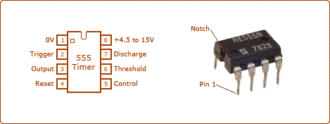


 The reflector circuit consists of Light dependent resistor (LDR), timer IC (NE555), some bright LED’s and Transistor (BC549) which is used as buffer. In this project 555 timer is configured in oscillatory mode.
When ambient light is dim a potential drop occurs across the light dependent resistor (LDR) below the level set by VR1. Due to this the reset terminal (PIN4) of NE555 goes high to enable the oscillator.
In other words we can say that in the presence of light, the resistance at PIN4 of IC1 is very low. Hence no signal is passed to PIN4 of IC1 so the voltage at pin 4 becomes equal to zero. As a result of this low voltage the circuit remains OFF and in the darkness vice versa occurs so PIN4 of IC1 becomes high and we get the output. 


this circuit can also be used as emergency night light, which puts on automatically.
Read more ...

August 10, 2014

battery charger circuit & battery level indicator with low battery recharge alarm

battery charger circuit & battery level indicator with low battery recharge alarm

This is a simple circuit of 12V rechargeable smart battery charger circuit. You can use this best battery charger circuit as car battery chargers, Inverter battery charger, Emergency battery charger etc. Automatic indicator alarm circuit is also comes along with this battery charger schematic. The main advantage of this indicator is that a buzzer informs us when the battery needs recharge. This circuit schematic definitely helps for your daily life battery charging applications.

Circuit diagram of battery charger


Components required

  1. Transformer (230V to 15V or 110V t0 15V)
  2. Bridge rectifier (1N4007 x 4)
  3. Capacitor (470µF, 50V)
  4. Voltage regulator IC 7815
  5. 12V rechargeable battery
  6. Diode (1N4148)
  7. LED Zener diode 9V
  8. Transistor (BC547 x 2)
  9. Resistors (10kΩ, 1.5kΩ, 100kΩ Each ¼ Watt)
  10. Buzzer (12V)


Working of battery charger circuit

  • The charging circuit is build around voltage regulator IC 7815 and two transistors BC 548.
  • The main supply 230V or 110V is step down using a step down transformer, and then it is rectifiered and filtered out.
  • That DC voltage is fed to the voltage regulator IC 7815; the output will be regulated 15V.
  • 12 volt rechargeable battery is connected at the output of voltage regulator and it charges when main power is available.
  • This circuit indicates the charging status that is the LED1 is glows when the battery charged (Above 10.5V).
  • When battery voltage goes below a particular value LED1 stops glowing and the buzzer produces sound indicating that the battery has been discharged and it needs recharge.


Read more ...
Designed By Published.. Blogger Templates