Breaking News

Receive all updates via Facebook. Just Click the Like Button Below...

Showing posts with label transistor. Show all posts

September 17, 2014

Water Sensor Circuit

Water Sensor Circuit


This water sensor circuit is very sensitive to trigger and activate the audio visual alarm when wetness is sensed at its probes. This project is useful at homes to detect the water supply in the situations when the timing of water supply is not fixed. This circuit uses the 555 timer along with some sensor element which can detect moisture.
In this water sensor circuit based project, 555 timer works in astable mode. It is driven by the emitter current which is coming from BC548 transistor as this transistor has high gain. In astable mode IC 555 functions as an oscillator. So for 555 to work in full oscillator mode a high current is required so as to trigger it. As the probes sense the moisture on it, the transistor gets switched ON and small current starts flowing between the base and the emitter. When no moisture is detected i.e. in dry state it remains OFF.

Initially as the supply is switched ON, the voltage at output pin of 555 timer is 0V. At this stage transistor will not conduct as the emitter current is LOW. Pin8 i.e. Vcc of 555 timer is connected to the collector of the transistor. As the transistor is switched OFF there will be no supply to 555 timer. As the water is sensed at the probes, transistor gets into its saturation region and starts conducting. As a result 555 gets supply for its operation. Its operation starts very soon as it is in astable mode. Sound is produced because of output pulses at pin3 which drives the loud speaker.


An ON/OFF state switch is used to control the conduction. The probes should be made up of non reactive metal so that there will be no inductance or capacitance present. An alternative can also be there i.e. use of alternate copper wires. No base resistor is required in this circuit because the transistor is in switch mode. The impedance at the emitter or the oscillator circuit acts as current limit. 


Read more ...

October 3, 2013

Transistor Tester

TRANSISTOR TESTER

The simplest transistor tester uses a 9v battery, 1k resistor and a LED (anycolour). Keep trying a transistor in all different combinations until you get one of the circuits below. When you push on the two leads, the LED will get brighter. The transistor will be NPN or PNP and the leads will be identified:


The leads of some transistors will need to be bent so the pins are in the same positions as shown in the diagrams. This helps you see how the transistor is being turned on. This works with NPN, PNP and Darlington transistors.


Read more ...

April 26, 2013

transistor

Transistors

A transistor takes in a small electrical current at its base pin and amplifies it such that a much larger current can pass between its collector and emitter pins. The amount of current that passes between these two pins is proportional to the voltage being applied at the base pin.

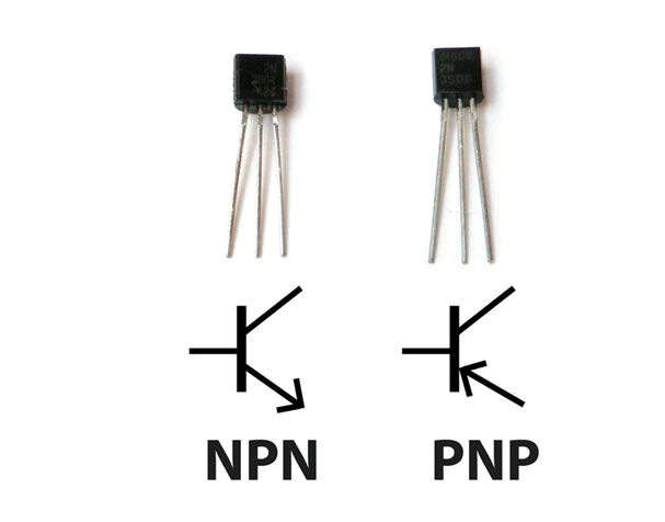
There are two basic types of transistors, which are NPN and PNP. These transistors have opposite polarity between collector and emitter. For a very comprehensive intro to transistors check out
 this page.

NPN transistors allow electricity to pass from the collector pin to the emitter pin. They are represented in a schematic with a line for a base, a diagonal line connecting to the base, and a diagonal arrow pointing away from the base.

PNP transistors allow electricity to pass from the emitter pin to the collector pin. They are represented in a schematic with a line for a base, a diagonal line connecting to the base, and a diagonal arrow pointing towards the base.

Transistors have their part number printed on them and you can look up their datasheets online to learn about their pin layouts and their specific properties. Be sure to take note of the transistor's voltage and current rating as well.

Read more ...
Designed By Published.. Blogger Templates