Breaking News

Receive all updates via Facebook. Just Click the Like Button Below...

Showing posts with label 555. Show all posts

September 17, 2014

Water Sensor Circuit

Water Sensor Circuit


This water sensor circuit is very sensitive to trigger and activate the audio visual alarm when wetness is sensed at its probes. This project is useful at homes to detect the water supply in the situations when the timing of water supply is not fixed. This circuit uses the 555 timer along with some sensor element which can detect moisture.
In this water sensor circuit based project, 555 timer works in astable mode. It is driven by the emitter current which is coming from BC548 transistor as this transistor has high gain. In astable mode IC 555 functions as an oscillator. So for 555 to work in full oscillator mode a high current is required so as to trigger it. As the probes sense the moisture on it, the transistor gets switched ON and small current starts flowing between the base and the emitter. When no moisture is detected i.e. in dry state it remains OFF.

Initially as the supply is switched ON, the voltage at output pin of 555 timer is 0V. At this stage transistor will not conduct as the emitter current is LOW. Pin8 i.e. Vcc of 555 timer is connected to the collector of the transistor. As the transistor is switched OFF there will be no supply to 555 timer. As the water is sensed at the probes, transistor gets into its saturation region and starts conducting. As a result 555 gets supply for its operation. Its operation starts very soon as it is in astable mode. Sound is produced because of output pulses at pin3 which drives the loud speaker.


An ON/OFF state switch is used to control the conduction. The probes should be made up of non reactive metal so that there will be no inductance or capacitance present. An alternative can also be there i.e. use of alternate copper wires. No base resistor is required in this circuit because the transistor is in switch mode. The impedance at the emitter or the oscillator circuit acts as current limit. 


Read more ...

September 16, 2014

Vehicle Indicator circuit

Vehicle Indicator circuit


The project illustrated below helps to find out nearby person or vehicle and make them visible to one another. It can be used in various applications for pedestrians, runners, bicyclists, motorcyclists, vehicles etc.
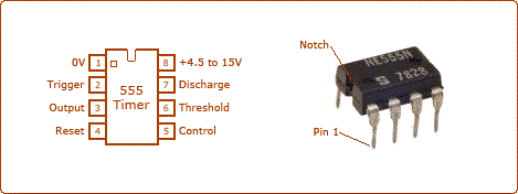
Most of the time during the night when the roads are badly lit the risk of accidents increases. Sometimes it happens that our vehicle breaks down and we need help. In such conditions this reflector can be used which automatically gets turned ON when it receives light from another vehicle passing nearby.  The circuit is based on 555 timer IC and uses a NE555 version of it. The pin diagram of the IC is shown in the image


 The reflector circuit consists of Light dependent resistor (LDR), timer IC (NE555), some bright LED’s and Transistor (BC549) which is used as buffer. In this project 555 timer is configured in oscillatory mode.
When ambient light is dim a potential drop occurs across the light dependent resistor (LDR) below the level set by VR1. Due to this the reset terminal (PIN4) of NE555 goes high to enable the oscillator.
In other words we can say that in the presence of light, the resistance at PIN4 of IC1 is very low. Hence no signal is passed to PIN4 of IC1 so the voltage at pin 4 becomes equal to zero. As a result of this low voltage the circuit remains OFF and in the darkness vice versa occurs so PIN4 of IC1 becomes high and we get the output. 


this circuit can also be used as emergency night light, which puts on automatically.
Read more ...

June 17, 2014

Cell Phone Controlled Home appliances

Cell Phone Controlled Home appliances

Many of us face problem when we out of our home like if we want to on the motor, so that when we reach home water will be filled in over head tank or we want to on other appliances like light fan etc.
Hence to solve this problem we have describe a simple circuit which will on your device or appliances remotely and it will become off automatically after preset time interval.
Many circuits have been developed so far to solve this problem but main advantage of this circuit is uses readily available components and this circuit is not expensive as well because this circuit is made using without microcontroller.

This circuit is based on two IC's namely MT8870 which is DTMF decoder IC and another is NE555 timer which is wired as monostable multivibrator with few more components like crystal, relay, resistors and capacitors.

How to operate a device remotely
In this circuit for operating a device we will require two cell phone, one will be with us from which we will call on the other cell phone which is connected to device. And other cell phone will be connected to the device in auto answer mode. For operating the device call on the cell phone which is connected to the device as this cell phone is in auto answer mode it will pick up the call automatically . When ring stop dial number 7 from the keypad of the mobile from which you are calling. Now the device connected to it with the relay start operating and will become off automatically after certain time period.

Working of circuit

Connect the cell phone  with the head phone or ear phone properly at mobile phone audio jack.  Now when you call on the mobile connected with device at the receiving end DTMF decoder IC will provide a high pulse at pin 15 after detecting the valid tone pair. This will trigger the pin 2 of IC2 and its output will go from high to low. This in turn make the output pin 3 of IC2 high and the transistor T2 connected to it start conducting because of this relay energise and device become on. The time period for which device remain on can be adjusted with the help of variable resistor VR1 and capacitor C4. By increasing or decreasing the value of variable resistor and capacitor  time period can be increased or decreased. This can be calculated by the below formula-
Time period = 1.1*VR1*C4 in seconds
In this circuit transistor T1 will only conduct when all the outputs pin 11, pin12, pin13 and pin15 will become high simultaneously with the help of diode D1 to D5. This can only be done by pressing the number 7 through DTMF decoder. The DTMF signal send from the dialler mobile end is decoded by the DTMF decoder and its respective BCD value appear at the output on pin 11, pin12, pin13. That's  why to on the device we are using number 7.


Read more ...

May 12, 2013

Noise making using 555 timer

Noise making using 555 timer


parts list:-

555 Timer IC
1K ohm - 1/4 Watt resistor
10K ohm - 1/4 Watt resistor
1M ohm - 1/4 Watt resistor
10uF electrolytic capacitor
0.01uF ceramic disc capacitor
Small Speaker
9V battery connector


This circuit is using a 555 timer chip to make noise using a speaker.
What is happening is that the configuration of components and connections on the 555 chip is causing pin 3 to oscillate rapidly between high and low. If you were to graph these oscillations, it would look like a square wave (a wave the alternates between two power levels). This wave then rapidly pulses the speaker, which displaces air at such a high frequency that we hear this as a steady tone of that frequency.
Make sure that the 555 chip is straddling the center of the breadboard, such that none of the pins might get accidentally connected. Aside from that, simply make the connections as specified in the schematic diagram.
Also note the "NC" symbol on the schematic. This stands in for "No Connect," which obviously means nothing connects to that pin in this circuit.
You can read all about 555 chips on this page and see a great selection of additional 555 schematics on this page.
In terms of the speaker, use a small speaker like you might find inside of a musical greeting card. This configuration can't drive a large speaker, the smaller the speaker you can find, the better off that you will be. Most speakers are polarized, so make certain that you have the negative side of the speaker connected to ground (if it requires it).
If you want to take it a step farther, you can create a volume knob by connecting one outer pin of a 100K potentiometer to pin 3, the middle pin to the speaker, and the the remaining outer pin to ground.


Read more ...
Designed By Published.. Blogger Templates