Pole Light Switch Circuit Schematic
 Power supply
The power supply is the typical capacitor limited charge pump type
that is zener regulated at 6.2V. Due to the lack of isolation, I was
careful to identify the return conductor so that the electronics
(including the LDR) would not be floating on the hot lead. For safety,
most of the testing was done using an isolation transformer. R1 must
absorb a high peak power transient current when power is applied, so a
carbon comp, ceramic comp, or wire wound resistor is recommended.
Maximum DC current available is 16mA. Actual load is about 6mA. My
application was 115V, 60hZ. For 230VAC, the components are indicated on
the schematic. In this circuit, +6V is the power return lead, and 0V
is the electronic circuit common—to visualize this, one must screw his
head on backwards…
LDR
The light dependent resistor (CdS photocell) that I used was in the
TO-5 package that is well adapted for poking through a hole and is held
in place with silicone rubber. The Clairex CL703M19 LDR that I used is
no longer available and I have been unable to locate the specs. The
DigiKey PDV-P8103-ND appears to be a reasonable choice, but may require
bias current tweaking to set the threshold.
555 Schmitt trigger driver
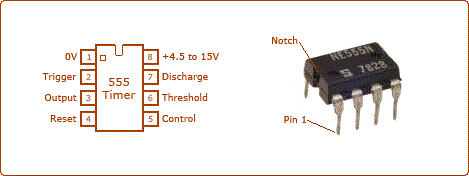
A TLC 555 was used as a voltage threshold detecting device with
hysteresis. Pin 7 drives the TRIAC gate directly via its open collector
output. This is a rather unconventional application. The CMOS version
is used to minimize power supply load—I tried a bipolar 555 and it
worked, but the power supply ripple voltage doubled to about 0.5VP-P.
Constant current bias—Threshold adjustment
Because the 555 has so much hysteresis, I feared that the ON &
OFF thresholds would be too far apart. To help reduce the hysteresis,
the LDR is biased by a current source. Q1 is wired as a current
source—its collector current does not vary with collector voltage. This
technique essentially increases the “gain” of the LDR. The current is
set via adjusting the emitter resistor (R3)—it drops about 0.37V.
C3 makes the circuit insensitive to rapid changes in light intensity. It takes about 60sec to turn on.
Logic TRIAC
The logic TRIAC is an interesting device. It can be triggered by
either a positive or negative gate current regardless of voltage
blocking polarity. For maximum sensitivity, I used negative gate
current. The device I used had an actual Igt (gate current sensitivity)
of 1.5mA that is well below the 5mA Max specification. However, gate
overdrive (5mA in my case) is recommended to assure that it fires at low
winter temperatures. Quencharc RC-1 is connected across the TRIAC to
help control turn-off voltage transients.
Choice of lighting
For the time being, I am sticking with the vintage incandescent
lamp—it is a matter of aesthetics. I will upgrade to LED technology
only when its color balance matches incandescent.
Photo gallery
 Glossary of undocumented words and idioms
(for our ESL friends)
tweaking –small adjustment (electronics)
to boot –idiom—literally, to kick around—In addition to—fringe benefit—“extra spending money to boot”
time being –idiom—the present time, presently, for now…