Breaking News

Receive all updates via Facebook. Just Click the Like Button Below...

Showing posts with label display. Show all posts

November 27, 2014

16x2 LCD Module

16x2 LCD

16x2 LCD means it can display 16 characters per line and there are 2 such lines. In this LCD each character is displayed in 5x7 pixel matrix. This LCD has two registers, namely, Command and Data.


LCD (Liquid Crystal Display) screen is an electronic display module and find a wide range of applications. A 16x2 LCD display is very basic module and is very commonly used in various devices and circuits. These modules are preferred over seven segments and other multi segment LEDs. The reasons being: LCDs are economical; easily programmable; have no limitation of displaying special & even custom characters (unlike in seven segments), animations and so on.

The command register stores the command instructions given to the LCD. A command is an instruction given to LCD to do a predefined task like initializing it, clearing its screen, setting the cursor position, controlling display etc. The data register stores the data to be displayed on the LCD. The data is the ASCII value of the character to be displayed on the LCD. Click to learn more about internal structure of a LCD.
 
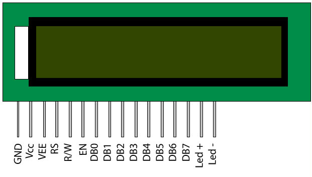
Pin Diagram: 


 Pin No
 Function
 Name
1
Ground (0V)
Ground
2
Supply voltage; 5V (4.7V – 5.3V)
 Vcc
3
Contrast adjustment; through a variable resistor
 VEE
4
Selects command register when low; and data register when high
Register Select
5
Low to write to the register; High to read from the register
Read/write
6
Sends data to data pins when a high to low pulse is given
Enable
7
8-bit data pins
DB0
8
DB1
9
DB2
10
DB3
11
DB4
12
DB5
13
DB6
14
DB7
15
Backlight VCC (5V)
Led+
16
Backlight Ground (0V)
Led-

The LCD works with voltage pulses only and that with precise timing and voltage levels. Hence special kinds of LCD drivers are developed to drive the LCD. Two or more of this kind of driver ICs together with the LCD screen forms LCD modules which are normally found in embedded systems.The LCD module makes a system stand-alone which can take input and display the corresponding output.
Read more ...

September 16, 2013

Voltmeter

Voltmeter


A voltmeter is an instrument used for measuring electrical potential difference between two points in an electric circuit. Analog voltmeters move a pointer across a scale in proportion to the voltage of the circuit; digital voltmeters give a numerical display of voltage by use of an analog to digital converter.
Voltmeters are made in a wide range of styles. Instruments permanently mounted in a panel are used to monitor generators or other fixed apparatus. Portable instruments, usually equipped to also measure current and resistance in the form of a multimeter, are standard test instruments used in electrical and electronics work. Any measurement that can be converted to a voltage can be displayed on a meter that is suitably calibrated; for example, pressure, temperature, flow or level in a chemical process plant.
General purpose analog voltmeters may have an accuracy of a few percent of full scale, and are used with voltages from a fraction of a volt to several thousand volts. Digital meters can be made with high accuracy, typically better than 1%. Specially calibrated test instruments have higher accuracies, with laboratory instruments capable of measuring to accuracies of a few parts per million. Meters using amplifiers can measure tiny voltages of microvolts or less.
Part of the problem of making an accurate voltmeter is that of calibration to check its accuracy. In laboratories, the Weston Cell is used as a standard voltage for precision work. Precision voltage references are available based on electronic circuits.

Analog voltmeter


A moving coil galvanometer can be used as a voltmeter by inserting a high-resistance resistor in series with the instrument. It employs a small coil of fine wire suspended in a strong magnetic field. When an electric current is applied, the galvanometer's indicator rotates and compresses a small spring. The angular rotation is proportional to the current through the coil. For use as a voltmeter, a series resistor is added so that the angular rotation becomes proportional to the applied voltage.
One of the design objectives of the instrument is to disturb the circuit as little as possible and so the instrument should draw a minimum of current to operate. This is achieved by using a sensitive galvanometer in series with a high resistance.
The sensitivity of such a meter can be expressed as "ohms per volt", the number of ohms resistance in the meter circuit divided by the full scale measured value. For example a meter with a sensitivity of 1000 ohms per volt would draw 1 milliampere at full scale voltage; if the full scale was 200 volts, the resistance at the instrument's terminals would be 200,000 ohms and at full scale the meter would draw 1 milliampere from the circuit under test. For multi-range instruments, the input resistance varies as the instrument is switched to different ranges.
Moving-coil instruments with a permanent-magnet field respond only to direct current. Measurement of AC voltage requires a rectifier in the circuit so that the coil deflects in only one direction. Moving-coil instruments are also made with the zero position in the middle of the scale instead of at one end; these are useful if the voltage reverses its polarity.
Voltmeters operating on the electrostatic principle use the mutual repulsion between two charged plates to deflect a pointer attached to a spring. Meters of this type draw negligible current but are sensitive to voltages over about 100 volts and work with either alternating or direct current.

VTVMs and FET-VMs

The sensitivity and input resistance of a voltmeter can be increased if the current required to deflect the meter pointer is supplied by an amplifier and power supply instead of by the circuit under test. The electronic amplifier between input and meter gives two benefits; a rugged moving coil instrument can be used, since its sensitivity need not be high, and the input resistance can be made high, reducing the current drawn from the circuit under test. Amplified voltmeters often have an input resistance of 1, 10, or 20 megohms which is independent of the range selected. A once-popular form of this instrument used a vacuum tube in the amplifier circuit and so was called the vacuum tube voltmeter, or VTVM. These were almost always powered by the local AC line current and so were not particularly portable. Today these circuits use a solid-state amplifier using field-effect transistors, hence FET-VM, and appear in handheld digital multimeters as well as in bench and laboratory instruments. These are now so ubiquitous that they have largely replaced non-amplified multimeters except in the least expensive price ranges.
Most VTVMs and FET-VMs handle DC voltage, AC voltage, and resistance measurements; modern FET-VMs add current measurements and often other functions as well. A specialized form of the VTVM or FET-VM is the AC voltmeter. These instruments are optimized for measuring AC voltage. They have much wider bandwidth and better sensitivity than a typical multifunction device.

Digital voltmeter

The first digital voltmeter was invented and produced by Andrew Kay of Non-Linear Systems (and later founder of Kaypro) in 1954.
Digital voltmeters (DVMs) are usually designed around a special type of analog-to-digital converter called an integrating converter. Voltmeter accuracy is affected by many factors, including temperature and supply voltage variations. To ensure that a digital voltmeter's reading is within the manufacturer's specified tolerances, they should be periodically calibrated against a voltage standard such as the Weston cell.
Digital voltmeters necessarily have input amplifiers, and, like vacuum tube voltmeters, generally have a constant input resistance of 10 megohms regardless of set measurement range.
Read more ...

August 18, 2013

Van de Graaff generator

Van de Graaff generator


A Van de Graaff generator is an electrostatic generator which uses a moving belt to accumulate very high amounts of electrical potential on a hollow metal globe on the top of the stand. It was invented by American physicist Robert J. Van de Graaff in 1929. The potential difference achieved in modern Van de Graaff generators can reach 5 megavolts. A tabletop version can produce on the order of 100,000 volts and can store enough energy to produce a visible spark.
A Van de Graaff generator operates by transferring electric charge from a moving belt to a terminal. First invented in 1929, the Van de Graaff generator became a source of high voltage for accelerating subatomic particles to high speeds, making it a useful tool for fundamental physics research.


Description

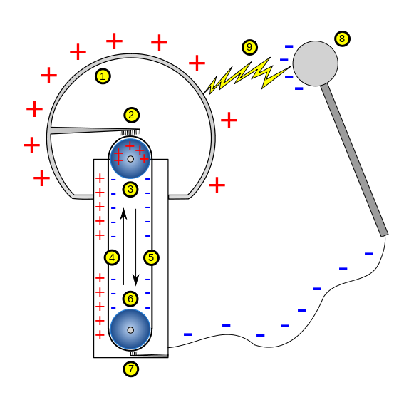
 A simple Van de Graaff-generator consists of a belt of silk, or a similar flexible dielectric material, running over two metal pulleys, one of which is surrounded by a hollow metal sphere. Two electrodes, (2) and (7), in the form of comb-shaped rows of sharp metal points, are positioned respectively near to the bottom of the lower pulley and inside the sphere, over the upper pulley. Comb (2) is connected to the sphere, and comb (7) to the ground. A high DC potential (with respect to earth) is applied to roller (3); a positive potential in this example.
As the belt passes in front of the lower comb, it receives negative charge that escapes from its points due to the influence of the electric field around the lower pulley, which ionizes the air at the points. As the belt touches the upper roller (6), it transfers some electrons, leaving the roller with a negative charge (if it is insulated from the terminal), which added to the negative charge in the belt generates enough electric field to ionize the air at the points of the upper comb. Electrons then leak from the belt to the upper comb and to the terminal, leaving the belt positively charged as it returns down and the terminal negatively charged. The sphere shields the upper roller and comb from the electric field generated by charges that accumulate at the outer surface of it, causing the discharge and change of polarity of the belt at the upper roller to occur practically as if the terminal were grounded. As the belt continues to move, a constant charging current travels via the belt, and the sphere continues to accumulate negative charge until the rate that charge is being lost (through leakage and corona discharges) equals the charging current. The larger the sphere and the farther it is from ground, the higher will be its final potential.

Another method for building Van de Graaff generators is to use the triboelectric effect. The friction between the belt and the rollers, one of them now made of insulating material, or both made with insulating materials at different positions on the triboelectric scale, one above and other below the material of the belt, charges the rollers with opposite polarities. The strong e-field from the rollers then induces a corona discharge at the tips of the pointed comb electrodes. The electrodes then "spray" a charge onto the belt which is opposite in polarity to the charge on the rollers. The remaining operation is otherwise the same as the voltage-injecting version above. This type of generator is easier to build for science fair or homemade projects, since it doesn't require a potentially dangerous high voltage source. The trade-off is that it cannot build up as high a voltage as the other type, that cannot also be easily regulated, and operation may become difficult under humid conditions (which can severely reduce triboelectric effects). Finally, since the position of the rollers can be reversed, the accumulated charge on the hollow metal sphere can either be positive or negative.

A Van de Graaff generator terminal doesn't need to be sphere shaped in order to work, and in fact the optimum shape is a sphere with an inward curve around the hole where the belt enters. Since electrically charged conductors have no e-field inside, charges can be added continuously. A rounded terminal minimizes the electric field around it, allowing greater potentials to be achieved without ionization of the surrounding air, or other dielectric gas. Outside the sphere the e-field quickly becomes very strong and applying charges from the outside would soon be prevented by the field.

Since a Van de Graaff generator can supply the same small current at almost any level of electrical potential, it is an example of a nearly ideal current source. The maximum achievable potential is approximately equal to the sphere's radius multiplied by the e-field where corona discharges begin to form within the surrounding gas. For example, a polished spherical electrode 30 cm in diameter immersed in air at STP (which has a breakdown voltage of about 30 kV/cm) could be expected to develop a maximum voltage of about 450 kV.

History


The fundamental idea for the friction machine as high-voltage supply, using electrostatic influence to charge rotating disk or belt can be traced back to the 17th century or even before (cf. Friction machines History)
The Van de Graaff generator was developed, starting in 1929, by physicist Robert J. Van de Graaff at Princeton University with help from colleague Nicholas Burke. The first model was demonstrated in October 1929. The first machine used a silk ribbon bought at a five-and-dime store as the charge transport belt. In 1931 a version able to produce 1,000,000 volts was described in a patent disclosure. This version had two 60 cm diameter charge accumulation spheres mounted on borosilicate glass columns 180 cm high; the apparatus cost only $90 in 1931.
Van de Graaff applied for a patent in December 1931, which was assigned to MIT in exchange for a share of net income. The patent was later granted.
In 1933 Van de Graaff built a 40-foot (12 m) model at MIT's Round Hill facility, the use of which was donated by Colonel Edward H. R. Green.

A more recent development is the tandem Van de Graaff accelerator, containing one or more Van de Graaff generators, in which negatively charged ions are accelerated through one potential difference before being stripped of two or more electrons, inside a high voltage terminal, and accelerated again. An example of a three stage operation has been built in Oxford Nuclear Laboratory in 1964 of a 10 MV single ended "Injector" and a 6 MV EN tandem.

Van de Graaff generators on display

The largest air-insulated Van de Graaff generator in the world, built by Dr. Van de Graaff in the 1930s, is now on permanent display at Boston's Museum of Science. With two conjoined 4.5 meter (15 foot) aluminium spheres standing on columns 22 feet (6.7 m) tall, this generator can often reach 2 MV (2 million volts). Shows using the Van de Graaff generator and several Tesla coils are conducted two to three times a day. Many science museums, such as the American Museum of Science and Energy, have small-scale Van de Graaff generators on display, and exploit their static-producing qualities to create "lightning" or make people's hair stand up. Van de Graaff generators are also used in schools and in science shows.

Comparison with other high voltage generators

Other classical electrostatic machines like a Wimshurst Machine or a Bonetti machine can easily produce more current than a Van de Graaff generator for experiments with electrostatics, and have positive and negative output. The less-insulated structures, however, result in smaller voltages.
Read more ...

June 20, 2013

Sony Smartwatch

Sony Smartwatch


         Specifications of Sony Smartwatch - Unisex (Black)

General
Type Smartwatch
Ideal For Unisex
Power Source Battery Powered
Style Code MN2

Body Features
Strap Material Rubber Strap
Strap Color Black
Case / Bezel Material Aluminium Case
Dial Shape Square
Clasp Type Buckle

Functions
Date Display Day and Date Display
Calendar Yes
Other Functions 1.3 inch OLED Display, Android Operating System, 10 m Bluetooth Connectivity, Music Player, Displays Messages and Emails, Social Networking Services, Access of Accepting and Rejecting Calls, Displays Pre-defined Messages, Notification through Vibration and Display, Calculator

Additional Features
Dust and Splash Proof, 20 mm Watchband Adapter, Charging with Standard USB Connector

Dial Dimensions
Width 36 mm
Height 36 mm
Thickness 8 mm

Warranty
6 Months Domestic Warranty

 Key Features

  • Black Strap
  • Square Dial
  • Buckle Clasp
  • Aluminium Case
Taking the popular and coveted touch technology on wristwatches to a whole new level in terms of touch and tech, is this awe-inspiring smartwatch from Sony. Featuring the highest levels of the latest Android platform, this highly sophisticated digital watch from Sony is all you need to keep your world at your fingertips.
Apart from its stunning design, this battery powered smartwatch from Sony comes fully armed with an arsenal of high-tech features and functions that is sure to blow you away. Being unisex, this smartwatch is a combination of all the right design elements that will easily suit both men and women alike.
Body and Design
Since this is no ordinary digital wristwatch, the form and design incorporated are just as cutting-edge as the functionality of this watch. The main part of this digital watch is its square dial that measures 36 mm in width and 36 mm in height with a super-slim 8 mm thickness. This dial houses a 1.3 inch OLED display, which also doubles as the watch's ultra-responsive touch interface, that lets you touch, tap and swipe to get desired response from your smartwatch.
Loaded with host of advanced technology, this dial comes surrounded by a significantly thick aluminium case, which gives this smartwatch the advantage of being dust and splash proof. This means that you can go on enjoying everything that this smartwatch offers, without worrying about how much damage caused to the watch by that accidental spill of water during dinner. This smartwatch stays securely attached to your wrist with its stylish rubber strap which operates a buckle clasp or with any 20 mm band, to which the dial can be fixed using its watchband adapter.
Functions and Other Features
Working on the popular Android operating system, this smartwatch from Sony is so advanced that it almost mimics every operation that can be done on an Android smartphone. Helping you to connect and pair this watch with your smartphone is its Bluetooth connectivity feature that has a maximum range of 10 m. This wireless pairing of your smartphone and the smartwatch, lets you experience and operate a wide range of smart features that includes music player, message and e-mail display, social networking, calculator, accept or reject calls and displaying pre-defined messages. Just like on your phone, all the notifications received come with display and vibration alert.
The watch also has the important and highly useful calendar function along with a day and date display, so you can easily plan your schedule, with nothing more than your smartwatch. The battery on this digital watch from Sony can be charged using a standard USB connector, making it a near perfect working replica of your smartphone.

price Rs. 6293(flipkart.com)

more pics


Read more ...
Designed By Published.. Blogger Templates